This tutorial shows you how to work with the Combine Files features in Acrobat 9. See what the all-new Acrobat DC can do for you.
Download a free trial of the new Acrobat.
Enabling 3D document-based communication and collaboration in Acrobat 9 Pro Extended
Learn how to use the 3D PDF templates, 3D commenting, and enhanced control over measurement markups.
Download this tutorial
![]() This tutorial is available in PDF.
This tutorial is available in PDF.
Download [2.9 Mb]
With the release of Acrobat 9, Adobe has taken the very specific Acrobat 3D offering--aimed at design manufacturing customers--and not only updated it with many new 3D capabilities and CAD translators, but also broadened its appeal to technical professionals in the manufacturing industry, as well as other users across many industries. The result is the new Acrobat 9 Pro Extended software.
In this first in a series of four articles, I will offer a quick overview and tutorial on three of the new 3D features that are sure to please technical and design users.
Convert virtually any CAD file into a PDF document using templates. Acrobat 9 Pro Extended enables users to convert designs from CAD applications, such as CATIA V4 and V5, NX, I-deas, SolidWorks, Pro/ENGINEER, Autodesk® Inventor and many others into rich, interactive Adobe PDF documents by placing CAD data in the context of a PDF template. PDF templates allow users to communicate and collaborate with project teams in a more effective, consistent and engaging manner. Not only can users place 3D design content into a PDF, but now they can place it in the context of a company/group template that can contain company logos, specific project titles and contact information, and much more.
See Figure 1 as an example of sharing 3D-design data in the context of a PDF template

Create a PDF Template

You can create your PDF from any application you want and then add to it a 3D placeholder to make a 3D-PDF template. In the PDF template example below, we used Microsoft PowerPoint to create a one-slide presentation.
-
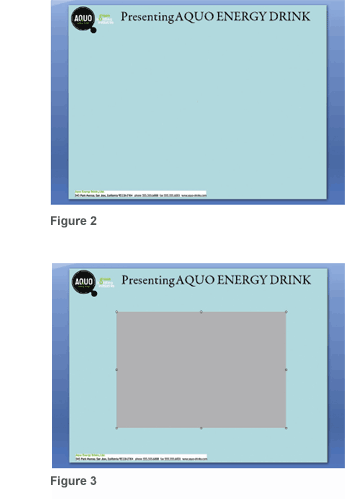
Using Microsoft PowerPoint, you can insert a company logo, project title, contact information or any other information you want place into a template, as shown in Figure 2.
-
Once you’ve placed your images and text, select the Acrobat tab from the top menu.
-
Click on
 Embed 3D icon.
 -
A new Add 3D data dialog box enables you to place 3D content into a PowerPoint slide.
-
Click OK.
-
You’ll see a gray square appear that represents the area where 3D content can be displayed.
-
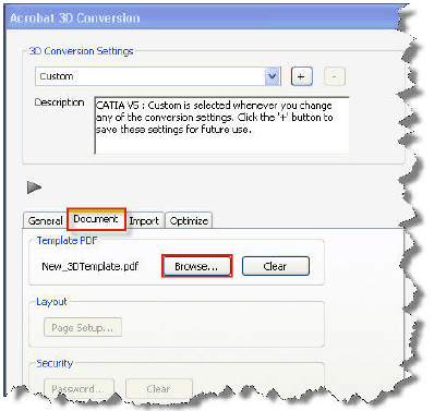
Drag the gray square into the center of the PowerPoint slide. You can also resize the gray area by dragging the edges of this gray square as shown in Figure 3.
-
Save the file as New_3DTemplate.PPT.
-
Convert to PDF by using the Create PDF icon.
-
Exit PowerPoint and Acrobat.
You’ve just created a PDF template.
Convert CAD data into a PDF using a PDF template

Now you can convert any sample 3D CAD file into a PDF by using the template we just created.
-
Launch Acrobat 9 Pro Extended, click Create > PDF from File, browse to any folder that contains a 3D CAD file.
-
Select the CAD file and click on Open.
-
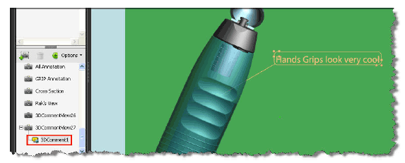
A conversion dialog box will appear. Select the tab named Document, as shown in Figure 4.
-
Select the Browse button in order to select the newly created template New_3DTemplate.pdf.
-
You can also select the Import and Optimize tab to control how the CAD data is converted to PDF.
-
Select OK to start the conversion process.
-
Save the file.
You’ve just created a PDF that contains 3D content in the context of a PDF template.
3D Commenting
With Acrobat 9, users have three ways to add comments to a 3D model:
-
Use the existing Comments and Markup toolbar
 to add a variety of comment types to a 3D view.
 -
Traditional sticky-note comments added to a 3D model are associated with specific views that are defined when the comments are added. For example, if the 3D model is rotated or moved, the comments are no longer visible.
-
Use a new method to convert a 3D measurement into a comment (This topic will be covered in Part II of this series).
-
Use the new 3D Comment Tool
 icon located on the 3D toolbar to add comments to specific parts of a 3D model.
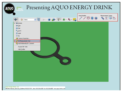
You can use 3D comments to easily draw attention to specific areas of the 3D model and enable all reviewers to have greater visibility to your comments, feedback and suggestions. Comments created by using the 3D Comment Tool are like measurements in that they are attached to a specific part of the 3D geometry. As the model is manipulated, measurements and 3D comments maintain perspective in relation to the other elements in the scene.
When you add 3D comments to the default view of a model, a new view--called 3DCommentView--is created. 3D comments added to other views are listed as components of that view in the model tree. You can edit and remove 3D comments the same way you edit and remove measurements.
Add a 3D comment
-
Open any PDF file containing 3D design data.
-
Click the 3D Comment
 icon on the 3D toolbar.
 -
Click an area on the model where you want to add a 3D comment, as shown in Figure 5.
-
Move the cursor to determine location of 3D Comment.
-
Click to accept positioning.
-
In the Enter Comment String dialog box, type your comment. Click OK.
-
Hit the
key to exit the command.

Figure 5
You can also move the location of the 3D comment at any time by grabbing the bottom right grips of the 3D comment area. Further, you can resize it by grabbing the upper left grips.
Save measurement markups
Users of Acrobat 9 Pro Extended and Adobe Reader will have more control over measurement markups than with the previous release. They will be able to easily adjust placement of measurements after creation, as well as save the measurements as a view when the file is saved so that they can be reviewed and annotated like other types of comments.
-
From Acrobat 9 Pro Extended, open any 3D PDF that you’ve created.
-
Ensure that the 3D content is enabled. That means you should be able to spin the model around.
-
You should see a 3D toolbar appear.
-
Choose Part Options> Isolate to isolate any one model in your PDF.
-
From the 3D toolbar, select 3D measurement Tool to invoke the measurement tool, as shown in Figure 6.
-
A new toolbar will appear that enables you to select the Snap points and Measurement Types you wish to perform.
-
Select the 3D Snap to Radial Edges icon from the Snap Enables tools and the 3D Radial Dimension icon from the Measurement Type tools.
-
Left click on your 3D model.
-
Click again to select the dimension you wish.
-
Move the mouse to the upper right to locate the dimension and left click to place the dimension.
-
A new dimension has now been created.
-
You’ll also notice a measurement view has been created in the model tree.
-
If you save this file, the measurement will be saved as part of the file.

Figure 6
In part two of this four-part series, I’ll cover some other key features, including exporting your work to a variety of neutral formats, 2D vector/raster files, or saving your work as an Adobe PDF. I will also describe the new Adobe 3D Reviewer application that is included with Acrobat 9 Pro Extended to merge heterogeneous CAD formats into one assembly; measure and section on precise geometry; compare a revised design to an earlier version; and create exploded views, animations and balloons.
Products covered: |
Acrobat 9 |
Related topics: |
Combine Files |
Top Searches: |
Create PDF combine files into one PDF Rearrange PDF pages |
Try Acrobat DC
Get started >
Learn how to
edit PDF.
Ask the Community
Post, discuss and be part of the Acrobat community.
Join now >

0 comments
Comments for this tutorial are now closed.
Comments for this tutorial are now closed.