This tutorial shows you how to work with the Combine Files features in Acrobat 9. See what the all-new Acrobat DC can do for you.
Download a free trial of the new Acrobat.
Manipulating a 3D PDF file using Acrobat 9
Learn how to enrich your Acrobat 3D PDF presentation with specified views, display objects contained within the model using Acrobat 9.
In this tutorial, learn how to enrich your Acrobat 3D PDF presentation with specified views, display objects contained within the model, and include measurements and comments.Placing a 3D model into a PDF file adds another dimension of information (pun intended). Adding a model is only one part of the Acrobat PDF 3D experience.
Last month, I described how to add 3D content to your PDF files via the source document or through Acrobat 9 Pro Extended. Enrich your presentation with specified views, display objects contained within the model, and include measurements and comments.
The view from here…
…Or from here, or there. A 3D image differs dramatically from what you see in a "regular" image. Unlike a traditional image displaying a single perspective, a 3D image lets you manipulate the model to view from any angle or side. Sometimes the model's author assigns views, stored with the rest of the model's information. You can use the provided views, or define your own when creating the PDF document or later in Acrobat 9 Pro Extended.
Pre-configure model views
Today's sample file started from a blank PDF document. Drawing a marquee on the blank page with the 3D tool activated the Insert 3D dialog box. To define the views before creating the model, choose the Add Default Views checkbox, and choose an option from the drop-down list (Figure 1).
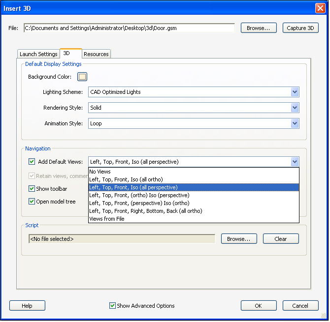
Figure 1: Specify views as part of the model conversion process.
Note: Read about choosing basic model settings in my previous article.
Once the model activates, you may see the Model Tree and Views panel display on the program window depending on the selections made when inserting the file (Figure 2).
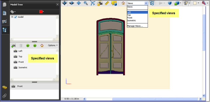
Figure 2: Activate the model to display the selected features.
You'll also find the views available in the drop-down list on the 3D toolbar.
Create and manage views
The sample project contains a model of an ornate door. The views include a Top view, which isn't of much value as a named view in this case, but doesn't include a Back view, which would be useful. To add an additional view via the Model Tree panel, follow these steps:
- Position the model as desired using the manipulation tools in the 3D toolbar.
- Click Create View in the Model Tree panel to display the View Properties dialog box (Figure 3). Here you'll find a list of display settings ranging between lighting to camera properties. To save time, click the Don't display this dialog on the "Create View" button check box to maintain the default choices. Click OK to close the dialog box and add the NewView view to the end of the view list.
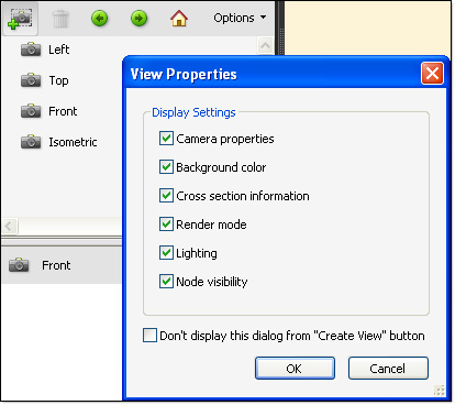
Figure 3: Add a new view and specify its properties.
- Click the default name to activate it and enter a replacement name.
You can add, delete and rename views on the Model Tree panel. However, to reorder the views, click the Views drop-down arrow on the 3D toolbar and select Manage Views to open the Manage Views dialog box (Figure 4). Select a view on the list, and use the commands to reorder the list, rename or delete content. If you've set the model's display prior to opening the Manage Views dialog box, you can add a new view, too.
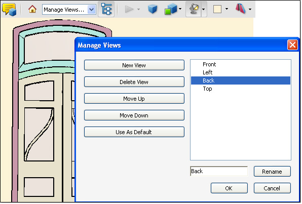
Figure 4: Modify the view’s details.
Travel through a model
Once your views are in place, click the Next View or Previous View buttons in the Model Tree panel to move through your set of views (Figure 5).
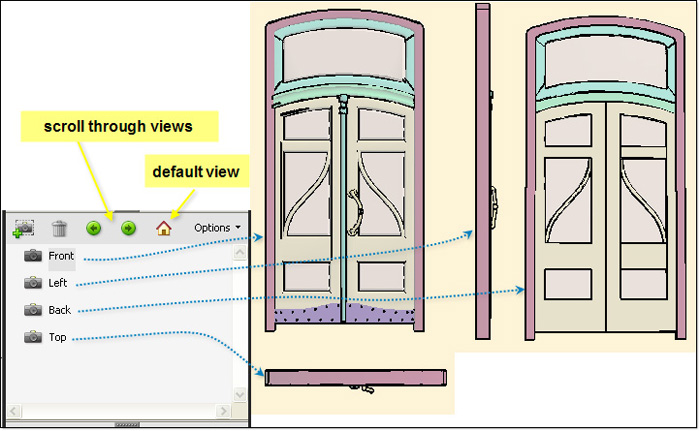
Figure 5: Scroll through your model views.
Beisdes static viewing of your model's views, you can use the Walk or Fly tools to animate the process. Neither walking or flying is of much value in a model like the door; it’s better used for models like rooms or buildings.
The Walk tool maintains a constant elevation as you pivot horizontally, or move forward/backward in the scene.
Right-click the model to open the shortcut menu and choose Tools > Walk to activate the tool. Alternatively, in the 3D & Multimedia preferences, select the Consolidate tools on the 3D Toolbar to include the Walk tool in the list (Figure 6).
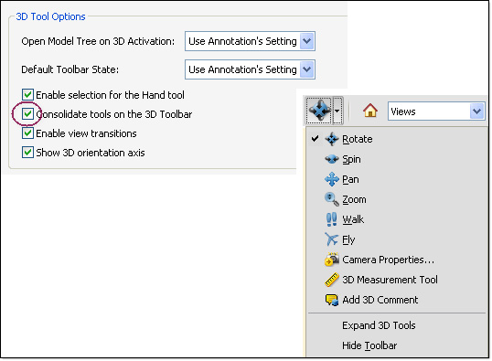
Figure 6: Consolidate the tools to include the Walk tool.
The Fly tool lets you examine your model using the camera view's surface orientation. A fly-through isn't optimal when viewing a model like the door, but is superb for checking out a landscape model. In Figure 7, using the Fly tool moves the view closer to the model along the same axis as the camera's display.
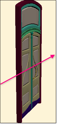
Figure 7: The Fly tool display uses the camera view's orientation.
Select the Fly tool on the 3D toolbar and try these maneuvers:
- Click the mouse button and drag to turn the camera view—the magnification increases as you approach the object
- Right-click and drag to turn without modifying the magnification
- Use the mouse scroll wheel to zoom along the camera view
View specific items
The sample file contains a simple model. As each component uses its primitive name, such as sphere or line as its name, working in the Model Tree has limited value (there's no point in exporting the model data as XML, for example) but offers handy viewing features, regardless of the model's complexity (Figure 8).
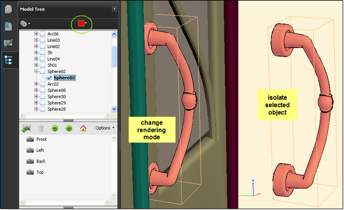
Figure 8: Select and manipulate objects.
Here are some model features to try:
- Chooose an object in the Model Tree and choose an alternate rendering mode on the shortcut or Options menus. The left model section shows the door as a shaded illustration against the solid rendering of the rest of the model.
- To isolate a selected object, choose Isolate on the shortcut or Options menus.
- Click the color swatch on the Model Tree toolbar to open a set of color swatches and choose an alternate color to use for highlighting the object on the model.
In a 3D model, adding a measurement automatically adds a measurement view, like MeasurementView5 shown in Figure 9. The measurement shows the distance between the surface of the door to the leading edge of the door handle. The model displays the measurement value, although it may be difficult to read at this point.
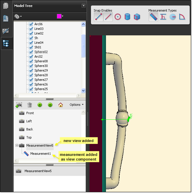
Figure 9: Measurements become new views automatically.
Note: Before you take a measurement, specify the model units, rendering mode, camera view, lighting and so on, as the measurement view includes these settings.
You can add as many or as few measurements as you like. The sample project includes three incrementally numbered measurement views. Each time you add a view and measurement, Acrobat lists the details as a child component of the view.
Add comments
You can add comments to a 3D model in three ways. Rather than leaving a measurement as is, convert it to a comment associated with the view. If you don't have a measurement, you can attach a 3D comment to a particular view instead. Finally, you can use tools on the Comments & Markups toolbar.
Convert a measurement
To create a comment from a measurement,click the measurement component (named Measurement1 by default). Click the Options menu on the View toolbar on the Model Tree panel, and then choose Convert to Comment. When generated, the comment displays in the Comments panel, and details show on the lower section of the panel (Figure 10).
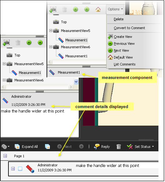
Figure 10: Convert a measurement to a comment.
Insert a 3D comment
You don't need a measurement to add a comment, of course. To add a 3D comment, set the view and other details as you wish. On the 3D toolbar, click the 3D Comment tool, then click the insertion point on the model where you want the comment to point. Drag and release the mouse to insert a comment location. Type your comment in the Enter Comment String dialog box, and click OK to insert the comment. On the Model Tree panel, you'll see a new view added, named 3DCommentView followed by the next view sequence digit by default, with the comment text as a component of the comment (Figure 11).
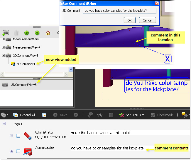
Figure 11: Insert a 3D comment in a special view.
Add a generic comment
Rather than using the specific 3D Comment tool, you can use any of the Comment & Markups tools. In Figure 12, for example, you can see a Rectangle drawing comment shown on a particular view. The comment includes an attached pop-up note, shown both on the document pane and in the Comments panel.
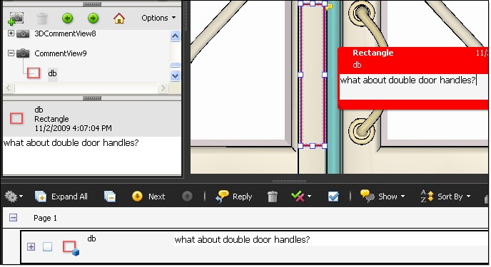
Figure 12: Insert a generic comment in another special view.
Notice another new view in the Views area of the Model Tree panel, again named 3DCommentView. The details area at the bottom of the panel shows the comment's contents.
Tip: If you don't want a comment associated with a particular view, click the page outside the 3D model's area.
The final view
Clearly, you can have a lot of activity in a 3D PDF document, even one as simple as a door. Rather than displaying all the views and comments in your Model Tree panel View area, filter the list to show just the comments (and measurements). To filter the list, click the Options menu's arrow on the View toolbar and select List Comments. To return to the full list, toggle off the List Comments check mark.
Products covered: |
Acrobat 9 |
Related topics: |
Combine Files |
Top Searches: |
Create PDF combine files into one PDF Rearrange PDF pages |
Try Acrobat DC
Get started >
Learn how to
edit PDF.
Ask the Community
Post, discuss and be part of the Acrobat community.
Join now >


0 comments
Comments for this tutorial are now closed.
Comments for this tutorial are now closed.